Monday, July 20, 2015

Extending an EMF Fuzz Testing Framework with support for UML

Extending an EMF Fuzz Testing Framework

with support for UML


Introduction

Randomly or pseudo-randomly generated data is useful in many application areas including software testing and software security. Using this kind of data as input to test software applications, helps improving their quality by increasing code coverage. In the area of model engineering there, currently, exists only very few frameworks that support the generation of UML (Unified Modeling Language) models. Generating such models would help testing software which expects UML models, with or without applied UML profiles, as input. In this blog we present an extension of an EMF (Eclipse Modeling Framework) Fuzz Testing Framework to support UML model generation including UML profiles.

What is Fuzz testing?           

The idea of Fuzz testing is to test software by using (pseudo-)randomly generated data as input in order to find inputs that cause unexpected behavior of the system under test. Using randomly generated input for testing helps improving software quality by increasing code coverage. Therefore, errors can be detected, which would be hard to find with other software testing techniques or manual input data specification. Reproducibility is a very important property of automated tests because it is necessary to reproduce an error in order to analyse and correct it. Additionally, the costs per found error can be significantly decreased. The generation of pseudo-random input is performed by a so called Fuzz generator.
               

Fuzz testing in Model Engineering

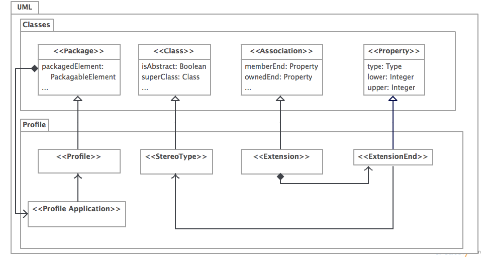
Fuzz Testing can also be applied in the area of model engineering, in which the generated inputs are models. Current Fuzz Testing Frameworks do not support the generation of UML models and UML models including UML Profiles. EclipseSource developed a generic Fuzz Testing Framework, which can generate EMF models, for testing EMF tools. Theoretically, this Fuzz Testing Framework should support generation of UML models as well. This assumption is based on the fact that Ecore is the meta-meta model (M3) used in Eclipse while the EMF-based implementation of UML is located in the metamodel layer (M2). Therefore, UML models should be accepted by the framework. However, there are a few problems which have been the starting point for our project.

Our goals

Current Fuzz Testing Frameworks have problems with generating UML models. Our first goal was, therefore, to extend the EMF Fuzz Testing Framework to work with UML models. Furthermore, our second goal was to extend the framework in such a way, that it also works with UML models including UML Profiles. As an additional goal we wrote a framework documentation to support our development process and help further developers to understand the framework quicker.

The Fuzz Testing Framework

As mentioned before, Fuzz testing is about pseudo-randomly generating input data and running tests with this data. Therefore, a test is not written with concrete input data, but with parameters which control the generation process. Parameters specify, for example, the number of test runs, size of the generated models, number of mutations per test run and the model of which instances should be created.
Therefore, the following components are needed to execute a test with the EMF Fuzz Testing Framework:
  • The DataProvider injects different model instances into the test case.
  • The JUnit TestRunner repeatedly runs the same test with different data.
  • The ModelMutator provides different model instances to the DataProvider.
To specify the parameters in the EMF Fuzz Testing Framework a FuzzConfig file is used.
The FuzzConfig file specifies the following parameters:
  • seed: Used for the pseudo-random generation in order to ensure reproducibility.
  • count: Specifies the total number of test runs.
  • testClass: References the corresponding fuzzy test class.
  • id
  • minObjectsCount: Specifies the minimum number of objects of the generated model.
  • mutationCount: Number of mutations to be performed.
  • ePackage: The model mutator generates models with instances of EClasses declared in this package.

Challenges & Results

After setting up the project, we realized that there was only code documentation and no framework description. In order to get familiar with the framework and to help further developers we decided to define a framework description as an additional goal. Next, we started with the implementation by trying to mutate UML2 models instead of Ecore models which failed due to various errors, like missing UML datatypes and wrong return values. One issue we worked on for a rather long time is closely related to the implementation of profile mutations. UML2 uses the class Model for applying and accessing profiles. An adaption which highly eases the implementation of profile mutations was thus to inject the generated model into a framework field of type Model instead of type EObject. We solved this issue by declaring the root object’s EClass (Model) in the fuzzy config file.

After we corrected the errors mentioned, we tried to extend the framework in order to enable the application of UML Profiles. The main part here was to develop custom mutations to apply and unapply the concepts of UML Profiles. The mutations we were working on are therefore:
  • ApplyProfileMutation
  • UnapplyProfileMutation
  • ApplyStereotypeMutation
  • UnapplyStereotypeMutation
In ApplyProfileMutation we first of all randomly generate a profile with a random number of stereotypes, having a random number of attributes (with randomly selected types). After that, the metaclasses of the model (to which the mutation should be applyed) are randomly extended by the previously generated stereotypes. This step is required in order to indicate which elements of the model can later have stereotypes applied. Finally, the generated profile is applied to the model. UnapplyProfileMutation randomly selects one already applied profile, and unapplies it. This can easily be done by using UML2’s method unapplyProfile.
                   
ApplyStereotypeMutation is the most interesting but also the most complex mutation. In this mutation, first of all, all elements which have applicable stereotypes have to be identified. We initially concentrated on applying stereotypes to classes, attributes and references. After checking these features for applicable stereotypes, a random number of stereotypes is selected and applied. Similar to the procedure of applying stereotypes, in UnapplyStereotypeMutation, we search for all features which have applied stereotypes, and unapply a random number of stereotypes.

To sum up, we wrote a framework documentation not only for our purpose but also for further developers who are working on the framework. The framework description is split up into three parts. The first part, Basic Overview, is for people whose aim is to use the Fuzz Testing Framework. In the second part we describe how a concrete Fuzz test can look like. A more technical description can be found in the third part where we describe the framework in greater detail for future developers who want to extend the framework and, therefore, need a deeper understanding of its architecture and how it should be extended.
Furthermore, we extended the EMF Fuzz Testing Framework for generating UML models.
After being able to generate UML models using the generic framework, we finally implemented the profile mutations for randomly applying and unapplying both profiles and stereotypes.        

For more detailed information on our project, we kindly refer the interested reader to our full report and the source code of the developed mutations.

Wednesday, July 08, 2015

SHACL4P: Shapes Constraint Language (SHACL) Plugin for Protégé Ontology Editor

Context & Motivation

Semantic Web is Tim Berners-Lee's vision to have information on the World Wide Web understandable for both humans and machines. It could also be seen as a web evolution approach that aims to help users by making use of machines to process, deliver, understand, and interpret large amounts of data for various purposes in a meaningful way.

Ontologies, as one of the main pillars of Semantic Web Technologies (SWT), are an explicit specification of a conceptualization to enable knowledge sharing and reuse. An ontology can also be seen as a way of organizing and categorizing information with the goal of facilitating its access, use, and distribution among communities. The World Wide Web Consortium (W3C), as international organization that develops Web standards, has defined several important W3C recommendations related to Semantic Web, such as Resource Description Framework (RDF), RDF-Schema (RDFS), Web Ontology Language (OWL) or SPARQL Query Language (SPARQL).

There are two important characteristics of current ontology languages in the Semantic Web: Open World Assumption (OWA) and Non Unique Name Assumption (Non-UNA).
  • OWA means that one cannot infer that a statement is false based on its absence (it may exist in the real world but was not explicated yet). This is the opposite of the Closed World Assumption (CWA), where non-explicit information is expressed as false.
  • Non-UNA implies that individuals could have more than one identifier. In other words, two or more identifiers could point to the same entity. This is different to other knowledge representations (e.g., relational databases), which typically operate under Unique Name Assumption (UNA).
Figure 1 shows the effect of having these two characteristics (OWA and Non-UNA) within ontologies. Depending on the use cases, some applications may require ontology axioms to validate its constraints according to certain constraint definitions, instead of inferring new information from the axioms.
Figure 1 Constraint Checking Example using Current RDF Vocabularies

The Challenges

Semantic Web Technologies have been widely used within data centric applications in various areas, e.g., in Bioinformatics, System Engineering and Cultural Heritage. SWT provide an excellent platform to capture the axiomatic (structural) definition of data (e.g., SKOS for hierarchies and vocabularies; Resource Description Framework Schema and Web Ontology Language for class, property, and relationships definitions). 

Within several of these data centric applications, there is desire to go beyond axiomatic definitions. One example is the definition of constraints that must be satisfied by the instance data. However, due to the Open World Assumption and the absence of the Unique Name Assumption in SWT, it is difficult to define structural constraints of an RDF graph with the current set of RDF vocabularies (e.g., RDFS, SKOS, and OWL).

Recently, Shapes Constraint Language (SHACL) was proposed to address this challenge. There are other approaches aiming to address a similar challenge, most notably Pellet-ICV, RDFUnit, and SPIN. None of them have been accepted as a W3C recommendation, which is specifically important for practitioners since they want to rely on stable specifications for their applications. 

Shapes Constraint Language (SHACL) is an RDF vocabulary for describing RDF structural constraints. SHACL allows validation of RDF graph data according to its SHACL constraint definitions. At the moment, SHACL is a work in progress of the W3C RDF Data Shapes WG.

Currently, the integration of such structural constraints definitions and validations in ontology editors is only available using specific commercial products (e.g., Pellet-ICV within StarDog and SPIN within TopBraid Composer

SHACL4P: The SHACL Protégé Plugin

In order to address the challenge of providing support of defining and validating structural constraints over RDF graphs using an open source ontology editor like Protègè, we will introduce the novel SHACL4P, a SHACL plugin for Protégé. The source code of SHACL4P is available under github as two separate Java projects, the Protégé plugin and the SHACL engine.

Our approach

The basic idea behind our approach was to integrate Ontologies and their respective SHACL constraints in order to perform constraint violation checking through the SHACL validation engine (see Figure 2).
Figure 2: Basic concepts of the validation process
We designed the SHACL engine in a modular fashion to increase reusability, maintainability, and readability. Our implementation is focused around three main components that will fulfill the required functionalities, (1) the SHACL user interface, (2) the data transformation component and (3) the SHACL validation engine.
  1. The SHACL user interface inside Protégé is the point of engagement to the user. It provides a way to add SHACL constraints and other vocabulary to existing ontologies. Furthermore, it visualizes the results of the validation process in an user-friendly format.
  2. Data transformation is performed as the intermediate step between the input gathered from the user interface and the actual validation. As we are dealing with two different sets of data, the ontology resulted from Protégé ontology editor which is to be validated and the SHACL constraints to be validated against, it is necessary to bring them in a uniform format before the actual validation. Additionally, it is also because Protégé and SHACL engine are using different API (Protégé uses OWL API, while SHACL uses Apache Jena). In the inverse direction, the component is responsible for transforming the results of the validation engine, which are described in RDF form, to a POJO.
  3. The SHACL validation engine provides a framework that allows constraint checking on a testing domain. The result of this process is a RDF representation that either describes the constraint violations or evaluates the domain to be valid.
Graphically, SHACL4P is implemented as a workspace tab in Protégé consisting of 6 different views, as displayed in the following screenshot (Figure 3):
Figure 3: Screenshot of the SHACL Protégé Plugin
  1. The class hierarchy view (upper left corner) displays all classes of the ontology.
  2. Instances of classes are displayed on the lower left corner.
  3. The SHACL text editor (middle upper view) is used to define SHACL constraints and to start the validation by pressing the button Execute on the lower left corner of the view.
  4. The logging view (middle lower view) informs the user about validation errors, failed syntax checks and other similar events.
  5. The Turtle rendering view (upper right corner) represents the current ontology in Turtle syntax for easier detection of the needed vocabulary.
  6. The prefix view (lower right corner) lists all defined prefixes of the ontology. This view can be helpful when defining the prefixes for the SHACL definition.

Conclusion & Future Work

We developed a plugin implementation that we built on top of Protégé to provide users with the means to define, implement, and execute SHACL constraints against their Semantic Web data within an open source ontology editor.

As for future work, we are looking forward to implement the full (final) version of SHACL within our plugin. Furthermore, we want to perform a user-study evaluation to test usability of the solution prototype.

SPARQL 1.1 Integration for KOMMA

Overview


Our project is an extension for the Knowledge Modeling and Management Architecture (KOMMA), an application framework for ontology based software systems. It is based on the Eclipse platform and is therefore easily extensible. As KOMMA’s support for the execution of SPARQL queries is limited to SPARQL 1.0, we have extended its functionality by introducing full SPARQL 1.1 support using Apache Jena, a general purpose ontology modeling framework.

KOMMA


There were two particularly important factors why we decided to build on KOMMA: Functionality and Maintenance. Upon our first inspection, KOMMA’s feature set looked refined enough in order to be able to use it in productive environments.

The second major factor (i.e. Maintenance) is KOMMA’s up to date state of development, it offers a working Eclipse marketplace version 6 that ran right out of the box on Eclipse Luna which was another requirement that had to be satisfied.

SPARQL


SPARQL is a query language designed to retrieve and manipulate data stored in RDF graphs. SPARQL is considered as one of the key technologies of the Semantic Web and is widely used. It was standardized by the W3C RDF Data Access Working Group (DAWG)  has become a W3C Recommendation on 15 January 2008. It was later replaced by SPARQL 1.1 which has also been declared a W3C Recommendation on 21 March 2013. With SPARQL 1.1, several additions and extensions to the query language have been introduced. In addition to performing query tasks, it is now possible to output the query results in JSON, CSV and TSV formats. Also, the SPARQL query and update system can be provided as a service via HTTP as part of the SPARQL protocol.

Status Quo


According to KOMMA's documentation, it should already be able to parse and execute user entered SPARQL 1.0 and 1.1 queries on ontologies opened in the editor. By analyzing the source code of KOMMA, we discovered that the support of SPARQL 1.1 is limited to only two features (FILTER EXISTS, MINUS). All other SPARQL 1.1 features were not implemented. KOMMA uses its own implementation of SPARQL 1.0 and a partial implementation of SPARQL 1.1 instead of relying on an already existing library or framework. Our task was to analyze and enhance KOMMA’s ability to handle both SPARQL 1.0 and 1.1 queries.

Implementation


There are a three main reasons, why we used an already existing library or framework for our implementation:
  • Test Coverage:Since Jena is a project of the Apache Software Foundation it can be assumed that the implementation is of great quality and very well tested. 
  • Usage:The bigger the user-base the more, and also faster, potential bugs and / or features get fixed and implemented. 
  • Reinvention: Rewriting code for such complex specifications as SPARQL is probably a great learning experience but should not be of highest priority and has resemblance to reinventing the wheel.

Implementation Details


For our modification we first added the Jena framework together with its needed dependencies to one of KOMMA’s submodules in order to be able to use it for our SPARQL 1.1 integration. 

We used Apache Jena's QueryFactory class to parse and validate the user-entered string which gave us the opportunity to detect errors in queries and to help the user correcting them. One of the trickiest parts was to connect Jena with KOMMA's own model representation. For our specific case we used a default model and fed it KOMMA’s representation of the model as a ByteArrayInputStream which was quite tricky since KOMMA was not designed for such a use-case. The third major part of our implementation was the use of the QueryExecutionFactory which utilizes the output of the ModelFactory and QueryFactory to provide us a ResultSet to work with.

We also had to partially adapt KOMMA’s interface in order to integrate our newly implemented code and connect the user interface parts with our input and output parameters.


The image above shows KOMMA’s new SPARQL query interface after our modifications. The user is now able to enter any SPARQL 1.0 or 1.1 query in the input field and KOMMA will parse and execute the query over the ontology. The user also gets notified via a pop-up if the query contains any syntactic or semantic errors. If the query passes, it gets successfully applied to the ontology and the interface then displays the resulting output in the result table which is created dynamically for each individual query.


Transforming UML Profiles to EMF Profiles


Introduction


As Domain Specific Modeling Languages (DSMLs) have high design and implementation costs, UML profiles are getting more and more popular as an option to bridge the gap between DSMLs and general purpose modeling languages (GPMLs). UML profiles provide a generic mechanism for customizing UML to support domain specific needs. EMF profiles emulate UML profiles inside the eclipse modeling framework environment. In this blog post, we describe our project which consists of providing a model-to-model transformation from UML profiles to EMF profiles to help users evade having to create a new EMF profile from scratch when a UML profile specifying the same domain already exists.

Background


UML profiles are packages of related and coherent extensibility elements including stereotypes, properties (previously called "tagged values") and constraints. The following figure represents parts of the UML metamodel defining UML profiles. It's kept rather simple by abstraction to hide the true complexity shifting the focus on the meta-class "Stereotypes" and the association "Extension". We can see that a Profile consists of the Profile itself, a ProfileApplication, a Stereotype, an Extension and an ExtensionEnd.

Excerpt of the UML Profile metamodel

EMF Profiles can be integrated into the EMF environment to act as a counterpart to UML Profiles. The figure below is an abstract representation of the EMF Metamodel with a focus on the stereotype and the extension elements. Since Ecore does not natively support Profiles, the EMF Profile extension is needed. As depicted below, a Profile in EMF consists of a Profile, a Stereotype and an Extension. The ProfileApplication, however, is not part of the EMF Profile itself.

Excerpt of the EMF Metamodel
Excerpt of the EMF Profile metamodel


 Conceptual Mapping and Implementation


When transforming Profiles from UML to EMF we look out for similar concepts and map them accordingly so that no relevant information is lost after the transformation. The core concepts can be mapped as shown in the table beneath.


Table 1. Mapping general Profile concepts

Furthermore, when examining the metamodels of both sides two problems become noticeable. First, in UML an Extension is represented by the Extension itself which furthermore consists of ExtensionEnds. They hold the reference to a Stereotype and to a Class. The main purpose of ExtensionEnds is saving the corresponding references of an Extension. In EMF an Extension is represented only by one class. Thus, the references to a Stereotype and a Class are part of the extension. Second, the ProfileApplication in UML is part of the profile itself. In EMF however it is outside of the profile.

The transformation is carried out in two steps primarily to keep the original design rational of a defined UML Profile and to exploit metamodel-aware profile reuse mechanism as introduced by EMF Profiles. 
  1. Step 1: Map all needed UML concepts that a profile requires so it can be applied to a model to a set of generic Ecore classes in order to act as placeholders for future extensions.
  2. Step 2:  Map all the specific features and references of stereotypes defined by a UML profile to stereotypes of an EMF profile. Extensions to UML meta-classes are mapped to generic Ecore classes as produced in the first step.

Step 1: Mapping of UML Concepts to Generic Ecore EClasses

Generic classes are used as placeholders for future ecore model classes. The goal is to design them with a minimal set of necessary attributes and references so that the transformed profile can still be applied to them. These classes work as a generalization of future model elements that are extended by the profile. Therefore every attribute and reference they have limits the options of future modelling elements where the profile can be applied to. Consequently we analyzed the attributes and references of the native UML classes and tried to find the minimum set of features necessary, so that it can be used as a reference by the EMF Profile. We focused on the UML concepts that are used in the UML Profile Store. In particular we produced generic EClasses for the following UML concepts: Class, Property, Enumeration, EnumerationLiteral, Operation, DataType, PrimitiveType and ProfileApplication. The table below features an example listing the attributes and references of the generic class (It does not represent a mapping table).

Table 2 Details on the generic Class

Step 2: Mapping of UML Concepts to EMF Profile Concepts:

After producing the generic classes, they can  be used for supporting the mapping of the EMF Profile specific concepts such as the profile, the stereotype and the extension. The table below depicts the example of the mapping of stereotypes. Even though both Stereotype concepts serve the same purpose, some features are di fferent and could not be mapped. In particular there is no visibility in ecore. This information is lost after the transformation. Furthermore Constraints are not de fined in ecore. We solved this problem by transforming constraints into annotations and storing the name and the OCL expression as its value. This expression can then be evaluated and enforced by the OCL line editor in EMF.
 
Table 3
Table 3 Mapping Stereoptypes


Evaluating the Transformation

In order to evaluate the practical application of the transformation, we developed some samples of source models (inputs) and their respective expected target models (outputs). A comparison of the actual result of the transformation with the expected output serve as a benchmark for the degree of the practical application of the transformation. Furthermore, by varying modeling elements, their relationships and their numbers, so does their complexity. We also test the transformation using all existing profiles from the UML Profile Store as transformation inputs which are complete profile examples as used in the industry. Overall, we analysed the practical application of 20 transformed profiles from the UML Profile Strore and perceived  no unexpected behavior.