Tuesday, September 11, 2018

Model-Driven Vertical Integration: Transforming between Production System Models and MES/ERP Models

Introduction

Manufacturing companies usually run a number of different software systems to monitor and control their operations from business aspects to their production systems. A fundamental concept to describe the different levels of control is captured in the functional hierarchy model.

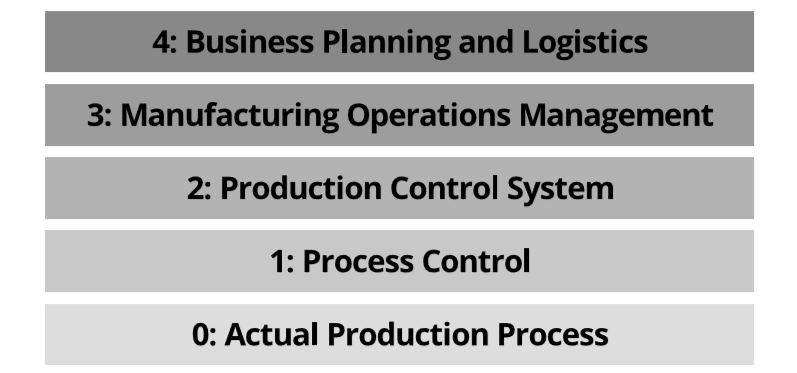
Functional hierarchy model for a manufacturing enterprise, depicting the five hierarchy levels in industrial automation.

This systems' separation leads to technical barriers. In order to overcome these barriers, international standards have been developed, such as the IEC 62264 series of standards that tries to harmonize levels 3 (MES) and 4 (ERP) and thus foster vertical integration.
In further steps, modern and smart manufacturing in production companies require deeply integrated IT systems to provide flexibility and rearrangement. Approaches like Industry 4.0 aim at flexible production network that additionally require horizontal integration across companies. Thus, there is also production related information exchanged in the network, which must be vertically forwarded to the corresponding service endpoints of the local production system.
To fulfill above requirements, two kinds of system integrations are required:
  1. Horizontal integration for the linking and seamless communication of systems in the network on the same hierarchy level.
  2. Vertical integration for the integration within one production system, from the business floor to shop floor. Vertical integration can go far beyond the manufacturing or management layers and down to programmable logic controllers and even single sensors. Practically all companies share the same vision for the future, automation and individualization of the complete manufacturing process, from product description, over order production to logistics and delivery. In order to create this vision in the real world, different business partners are required for executing specific processes, provide these capabilities in service and work with standardized horizontal and vertical information linking.
Model-Driven Engineering (MDE) is a software engineering development methodology that focuses on creating and exploiting domain models, which are conceptual models of topics related to a specific problem. MDE has developed a rich palette of tools and techniques for the description and manipulation of software models including model-to-model transformations, model validations, querying and many more.
In this blog post, we will showcase the application of Model-Driven Engineering in the field of automated production systems, focusing on vertical integration by aligning AutomationML, IEC 62264 and B2MML. For example, a digitized shop floor is much more flexible and open to adaptations when digital standardized system models are used, rather than it has been the case in the past when required rapid adaptations in the business models were necessary to provide up-to-date service descriptions.
Our digital shop floor is encoded in XML-based AutomationML (AML), for the MES to ERP integration we are using IEC 62264 (specifically, its second part) and its XML serialization B2MML. The focus in the implementation is on transforming between these three standards and extracting information into persistent document files.

Implementation

In this section we give an overview of the different transformation implementations between AutomationML, IEC 62264-2 and B2MML, based on the ATL Transformation Language for Model2Model (M2M) transformations and the Xtend Java dialect for Model2Text (M2T) transformations.

Implementation tasks overview

  1. ATL M2M Transformation: AutomationML <-> IEC 62264-2 pure.
  2. ATL M2M Transformation: B2MML <-> IEC 62264-2.
  3. Xtend M2T Transformations:
    1. 3.a AutomationML model to .aml document file.
    2. 3.b B2MML model to .b2mml document file.
  4. Additional Tasks:
    1. 4.a ATL M2M Transformation: AutomationML <-> IEC 62264-2 light.
    2. 4.b Unidirectional cross references from .aml document files to .b2mml document files.
The pure transformation considers all components and details, whereas the light transformation only transforms main components and leaves details to separate B2MML files which are referenced. The metamodels of AutomationML and IEC 62264 were provided in advance, whereas the B2MML metamodel was generated from an XML schema.

Conclusion

In our technical section we implemented model transformations, code generation and Java programs for adapting the model instances to achieve the goal that one single model is available in three different languages which are B2MML, IEC 62264 and AML and in their XML representation as files. The translation between all of these instances is very fast and can be used to improve collaboration between tools using one of the languages. One future task would be the implementation of bidrectional transformations between IEC 62264, AML and B2MML. With this improvement it would be possible to change between the languages very fast and so the model can always be adapted to the language currently needed. Other tasks which can be done after this project would be the changes in the transformations like the generation of real GUIDs or the transformation of other concepts in these languages which had been neglected such as transformations of ProcessSegmentCapabilityModel etc.


Tuesday, August 28, 2018

Analyzing robot behavior through model execution and 3D simulation: A case study on the Ozobot robot

by Hansjörg Eder and Christoph Fraller

Introduction

The goal of this project was to combine the model execution capabilities of GEMOC Studio with the 3D simulation facilities of Blender on the case of the Ozobot robot. This combination should enable the enhanced model-based analysis of robot behavior.

Ozobot is a small robot with an integrated battery and five color sensors on the bottom. The robot is programmable via sequences of colors (color codes). To create Ozobot programs, the OzoBlockly programming language and Web IDE can be used.


Project Overview


Within the project, we developed an executable modeling language for modeling the behavior of Ozobot robots using GEMOC Studio, GEMOC Studio is a language and modeling workbench built on top of the Eclipse Modeling Framework (EMF). The developed language definition artifacts comprise a metamodel defined with EMF Ecore, a graphical concrete syntax developed with Sirius, and an operational semantics implemented with Kermeta 3 (K3). Based on these language definition artifacts GEMOC Studio provides model execution facilities including model animation and model debugging.

The developed executable modeling language basically allows to model Ozobot behavior as a set of commands that are executed sequentially. During the execution of an Ozobot behavior model, the current command and the current position of the Ozobot will be displayed in the model animation.

For the visualization of the actual robot movements we created a 3D simulation with Blender, which is an open source software for 3D creation. This 3D simulation shows the robot movements as defined in a model created with our developed modeling language.

The model execution performed in GEMOC Studio controls the 3D simulation in Blender. This is achieved by sending information about the currently executed command from the model execution to Blender through an MQTT server.


Model Execution

In order to make models executable, one has to define the execution semantics of the modeling language. For this, we have used GEMOC Studio in this project, which offers the action language Kermeta 3 to define operational semantics. To provide model animation in GEMOC Studio that shows information about the progress and the state of the model execution, the graphical concrete syntax of the language needs to be extended with a so-called animation layer.

The figure below shows an Ozobot program with a set of commands. The current command is highlighted in the animation and also displayed in the second box on the right. Above this box, the current position of the Ozobot is displayed.


3D Simulation

The developed 3D representation of Ozobot consists of a black cylinder, a transparent black glass ceiling and a light under the glass ceiling. The environment consists of a grass area, which serves as the ground for the Ozobot. There are some boxes placed on the ground, which represent obstacles that Ozobot can shift away.

The simulation is controlled via Python scripts. We have implemented two scrips Controller.py and Server.py. Controller.py contains the logic of the Ozobot commands and will be executed at every frame. Server.py is only executed once and listens for incoming commands from GEMOC Studio that are transmitted via MQTT. Incoming commands are passed on to Controller.py for advancing the 3D simulation.


Future Work

Possible future work based on this project include:

  • Support for an extended set of commands
  • Implementation of a code generator for generating color codes out of Ozobot behavior models that can be used to program Ozobot
  • Establishing a bi-directional communication between Blender and GEMOC Studio
  • Improvements to the 3D simulation
    • Provisioning of additional environments
    • Support of effects like fragmentation of boxes
    • Implementation of logic behavior for Ozobot (e.g. Ozobot recognizes obstacles and avoids collision)

Resources

Monday, August 20, 2018

Towards Web-Based Modeling

by Patrick Fleck, Laurens Lang and Philip Florian Polczer

Introduction

Currently, model-driven engineering is usually done with the help of traditional Integrated Development Environments (IDEs) like Eclipse. The setup of such IDEs may be cumbersome and time-consuming. We explored the possibility that web-based IDEs combined with a Language Server Protocol (LSP) offer for model engineering. We developed a small domain-specific-language based on Xtext, based on an existing modeling project. Using Theia and a language server to provide programming language-specific features we enabled the web-based modeling with our language via any common browser. To further explore the opportunities of this approach we used Sprotty to implement a graphical modeling tool in our IDE.

The Workflow Constraint Language

The starting point of our work was the existing Papyrus Workflow Modeling Tool created by EclipseSource. It allows the modeling of a workflow with actors. We built a domain specific language based on this project which allows to define constraints for a workflow.

We realized the "Workflow Constraint Language" (WCL) with Xtext and Xtend. The idea is to define assertions between Actions in the Workflow, as well as between Actions and Actors. Therefore, the two possible assertions may look like this:

assert_activity "Activity1" always_before "Activity2"
assert_actor "Actor" is_actor_of "Activity1"

Language Server Protocol

The Language Server Protocol (LSP) is a JSON-RPC-based protocol that standardizes the communication between an integrated development environment and the server that provides the domain specific language. The overall objective of this is to enable a programming language support to be implemented and distributed independently of any given editor or integrated development environment. The integrated development environment, with which the user interacts and consumes the language service, acts obviously as a client and the server, that provides the language service. The client informs the server about the local changes of the user events, while the server responds with appropriate suggestions, error messages etc.
 
Communication throug LSP [1]

For setting up our Language Server, we used the Libraries LSP4J and JSONRPC. The Language Server itself acts as a predefined program unit, which is extended by language modules. These language modules are injected into the Language Server. In our case, we injected the created Workflow Constraint Language module, which was created with the Eclipse Modeling Tools by designing the Xtext language.

Theia

Theia is an extensible platform to develop full edged multi-language cloud and desktop IDE-like products with state-of-the-art web technologies. Theia provides both, for native desktop and web-based application, on the one hand and on the other hand a remote server. There exist the frontend and the backend, which communicate through JSON-RPC messages over WebSockets or REST APIs over HTTP.

Architecture [2]

Theia comes, similar to the Language Server, as a predefined program unit and is available via Node.js. We created a module for Theia, which is injected into the existing Theia application. The module itself is resposible for the communication with our Language Server. Furthermore, the Syntax highlighting is defined through the framework "Monaco".


Theia Application with example WCL-file

Sprotty

Sprotty is an open-source, web-based diagramming framework, which supports SVG, CSS and animations.
At the server side, the model corresponding to the WCL-file is translated into the sprotty model. Afterwards, the server sends the JSON representation of Sprotty's graph model back to the client.


Sprotty Model [3]


At the client, a module which is responsible for the interpretation of the graph module was created and again injected into the existing Theia application. This module renders the graph model into SVG-views.

Conclusion and Future Work

By migrating the Workflow Constraint Language from a standalone Eclipse-Module to a Web Based IDE through putting up a Language Server, a Theia client and extending the tools with graphical modeling approaches with Sprotty, we presented one way how web based modeling tools can be realized.
In addition to our work conducted during the project, the following points may be followed in the future:
  • Using Theia as an electron-based client IDE
  • Extending the atomic tests (assertions) of the language
  • Extending the graphical modeling capabilities by adding, removing and editing egdes and nodes

References

[1] What is the language server protocol? https://microsoft.github.io/language-server-protocol/overview. Accessed: 2018-06-10.
[2], [3] Business Informatics Group. https://www.youtube.com/watch?v= er9uxpb91y.
Accessed: 2018-06-21.

Wednesday, August 01, 2018

Enterprise Architect Sequence Miner

Christoph Hafner, Maximilian Medetz and Michael Wapp

Introduction

Nowadays, software or production systems create log traces in order to provide a way to track systems' execution. This allows system engineers to understand what the operating system was actually doing. One challenge, which arises with log traces, is that they are usually in a text-based representation (like TXT- or CSV-Files) and often very huge. Thus, it is hard to understand and analyze them and a better representation is sought.
To overcome this challenge one possible way is to use a graphical representation such as sequence diagrams described in the Unified Modelling Language (UML). These diagrams can be generated via a text-to-model transformation from the text-based log traces. The Figure 1 and 2 present the difference in simplicity on a short example of log traces. In Figure 1 the text-based representation is shown and in Figure 2 the same data is illustrated in a graphical representation. 

Figure 1: Log trace in text-based representation
Figure 2: Log trace in graphical representation (sequence diagram)
The sequence diagram in Figure 2 shows the interaction of objects (shown in the lifelines of the diagram) over a time frame. The interaction is presented by directed arrows that are either open, closed, solid or dashed. Open arrows with a solid line (like the second one from the top) depict that the message is an asynchronous message - which doesn’t require an answer from the receiver - while closed arrows with a solid line present synchronous messages - requiring an answer by the receiver. The answers are described by dashed lines with an open arrow at the end. If the message is sent to the same lifeline again a level is added to this lifeline showing that there are multiple responses required (this can be seen on the car lifeline in Figure 2).
The prototype implementation for transforming CSV log traces to sequence diagrams is based on an extension to the Enterprise Architect (EA) by Sparx Systems which is a tool for visual model designing used by businesses and software designers to support their model-driven development processes. EA provides an API which can be used for accessing and creating models from Add-Ins. This API was used by the prototype implementation to generate the result of the transformation in a UML sequence diagram.

EA Sequence Miner

The prototype named EA Sequence Miner is an EA Add-In written in C# using Visual Studio 2017. This post will give a short and general overview of the tool. For information about the code, a documentation on how to add the Add-In to the EA and to use the EA-API can be found in [1] (tutorial pages of Sparx Systems).
There are different requirements that should be fulfilled by the prototype implementation in order to improve related work like UML Miner Tool [2]. Some of the  main requirments are:

  • Support for asynchronous messages
  • Support for levels on a lifeline
  • Improved usability by providing error messages and information about the current state

The most important issue is the ability to transform a textual log-file to a model. In order to achieve this requirement, the text file should be in a CSV representation (separated by semicolons) and contain (at least) the following columns of data
  • CaseID: Identifying the corresponding case
  • Activity: Defining the corresponding activity which was logged by the soft- or hardware
  • Lifeline: Defining the lifeline (e.g. entity or object) to map the corresponding object in the diagram
  • MessageParameter: Additional parameters which are passed with the request
  • REQ/RES Attribute: Describing the request, response and async attributes needed for getting the direction of the message. These attributes further need to be mapped to the prototype for correct handling of the messages

The mapping between the imported CSV file and the prototype is done via a drop-down selection, showing all possible columns to match. Figure 3 shows the selection screen. In addition, a name for the diagram has to be set before proceeding to the next step.
Figure 3: EA Sequence Miner Selection Screen

The prototype code is structured into four parts, following the Model-View-Controller pattern.  First, the User Interface which is implemented as a Windows Form Application. Here the interaction with the user is handled. Second, the Event Log classes which represent the Log-Entries of the given CSV-File. Third, the Transformation part which is responsible for transforming the Log-Entries in an iterative manner into the model by writing it to the Enterprise Architect via the last package, the EA-Facade. This fourth package is following the Facade-Pattern and encapsulating the communication to the Enterprise Architect.

Conclusion and Further work

We showed a prototype implementation of an Enterprise Architect Add-In for transform text-based log traces to UML sequence diagrams. This approach solves the problem of understanding big log traces by converting them into human-friendly graphical representations.
The implemented prototype could further be enhanced by providing support for even longer log files with cycle detection and other separation techniques to keep the visual representation understandable. Further enhancements would be the support of different diagram formats and from user perspective more warnings, e.g., for incomplete log files.

References

[1] https://www.sparxsystems.com/enterprise_architect_user_guide/14.0/index/index.html
 
[2] Davydova, K. V., and Shershakov, S. A. Mining hierarchical uml sequence diagrams from event logs of soa systems while balancing between abstracted and detailed models. 28, 3 (2016).

Model Driven Engineering for the Internet of Things: A Systematic Literature Review

By Stefan Märzinger

Introduction


The Internet of Things (IoT) is maturing. Therefore engineers and researchers develop different approaches and applications and publish their research.
Some approaches are in the context of model driven engineering. To get a better insight about the combination of MDE and IoT we did a primarily systematic literature review.
For that purpose we defined the following research questions:
  • Which IoT concepts are tackled by MDE4IoT approaches?
  • Which MDE approaches/techniques are used in combination with IoT?

Motivation


The term “things" in the IoT context means a wide range of different devices like vehicles, wearable devices, sensors e.g., a humidity sensor and a lot more which are embedded with software and electronics so they can connect which each other and exchange data.
This large number of different devices leads to a big heterogeneity.

Another challenge is that devices are often very small and restricted in battery and computational power. Furthermore, they vary in the kind of hardware.

Additionally, devices are mobile and therefore can leave and enter an area at any point. The IoT application developers need to take this into account, e.g., by replacing a device that left the area of operation by another device with similar capabilities.   

To solve these challenges several IoT concepts were developed by researches and IoT application engineers.


Research Methodology


Based on 6 initial documents we familiarized ourselves with the topic. As next step different search queries on Google Scholar were tested.

The final search query was (“model driven engineering" OR MDE OR “model based" OR “model driven") (“internet of things" OR IoT).
The query does not focus on specific IoT concepts. Due to the use of quotation marks no papers were found that contains just single words but used in another context. For instance, Internet would return many publications without any context to Internet of Things.

In Figure 1 we show the research process to finally get 46 documents for analysis.

How the documents to analyis were selected
Figure 1: Search and screening process.


From the chosen query 50 papers were checked if they match “MDE in the field of IoT".
These 50 research papers are divided in 15 most recent papers on the search day April 11,2018, 15 most quoted papers and 20 most relevant papers accordingly to Google Scholar.

After filtering papers that did not fit our scope, 18 publications remained in our result set.
Additionally 1 paper from another tested query and 1 paper from the search for IoT-A architecture were added to the document for analysis.

Also a light form of snowballing was done to search for additional papers. By this way, we checked the references (especially in the related work) of the research papers and finally got 22 additional papers.

The selected 46 documents were analysed by reading the abstract and conclusion and the approach if something was not clear yet. Furthermore, figures, images, listings and noticeable headlines were taken into account.


Results


Quantitative Results

We identified 6 IoT concepts that were used together with MDE.

Table 1 shows the identified IoT concepts and in how many papers they were used. We found out that most of the listed publications cover more than a single IoT concept.


IoT Concepts and the Quantity of their usage
Table 1: IoT Concepts in relation to their representation in research papers, ordered
by occurrence.


Table 2 presents the used MDE techniques in the publications. 


MDE techniques and the Quantity of their usage
Table 2: MDE Techniques in relation to their representation in research papers, ordered
by occurrence.


Table 3 depicts how often an IoT concept is used with a MDE technique in the same publication. As limitation, we have to mention that it does not show if a MDE technique was used to implement an IoT concept.


Table 3: MDE Techniques combined with IoT Concepts.


Figure 2 illustrates the absolute number of publications per year.


Figure 2: Number of Publications per Year.


Quality Findings


Many presented approaches used web services like SOAP and especially RESTful web services to expose the functions and data of the IoT devices.

We found 2 large projects BIG IoT and IoT-A in our result set.
The BIG IoT project tries to build an ecosystem over multiple platforms.
In one BIG IoT paper, the authors mentioned that their ecosystem includes 8 platforms of different companies such as Bosch and Siemens.
One goal of BIG IoT is to support the transformation from an Off ering Description like JSONLD or GraphQL to a W3C Thing Description. Thus, the interoperability with, e.g., other MDE tools will be improved.

IoT-A project follows a similar approach by defining an architectural Reference Model to increase the interoperability of IoT applications and other tools.
With Papyrus for IoT, there already exists a modelling environment that uses IoT-A.
In addition, the IoT-A deliverable was the only publication in our result set where the interaction of a user with a device was modeled. In this context, the user can be a human or a digital entity like a service.

Furthermore, we found out that several different DSLs and specific IoT frameworks were used in the publications such as IoTML, SrijanLanguages, ThingML, UML4IoT, MDE4IoT and DDL.

Future Work


This work analysed how often specific MDE techniques were used in combination with IoT concepts. As a possible next step, we could analyse which tools and frameworks are exactly used for which IoT concepts and how big the relevance of already developed frameworks like MDE4IoT or UML4IoT is in the area of IoT.

Thursday, July 19, 2018

[Building Information Modeling] IFC to Ecore Transformation

Introduction:

Building Information Modelling is, in the field of the construction industry, an approach to build semantically-rich 3-dimensional digital models instead of “plain old” CAD models to fulfill different needs of different stakeholders.
The most widely used standard for exchanging BIM models in the industry is defined by the Industry Foundation Classes (IFC). IFC is a standardized data model developed by different domain experts to enable interoperability within the Architecture, Engineering, Construction and Facility Management industries.

Problem Description:

Using IFC software products in research as well as in real projects presents certain challenges – it’s complex, hard to understand for the users and has some consistency issues during import and export of real-world building data.

Many of above mentioned issues can be addressed by transforming this IFC metamodel into a smaller, easier to understand and use model, as an instance of a common linguistic meta-model, such as Ecore. The advantage of an Ecore model is not only a new class diagram, but rather the ability to use a very broad set of Ecore functionalities, such as code, entity and api generation, as well as the ability to check models regarding their syntactical and semantical correctness.

Our project, the transformation to the Ecore Model is a part (step 2) of the bigger picture shown below

The bigger picture
The bigger pictur

We used the Atlas Transformation Language (ATL) for this transformation. 

IFC Structure:

In general, the IFC specification consists of four different Declaration types: 
  • Type Declarations 
  • Entity Declarations 
  • Function Declarations 
  • Rule Declarations 

We focused on the transformation of Type and Entity Declarations and handled the rest as simple EClass “name-only” stubs. 

Type Declarations are similar to "typedef" or "value type" in common programming languages, and refer to a basic information construct, derived from: 

  • an Enumeration
  • a primitive (String, Integer, Real, Boolean) - aka Concrete Type
  • a selector of entites of types - aka Select Types 


Entity Declarations are similar to the term "class", and describe data structures. They are built in the following way (in the express notation)

ENTITY (*Name*) 
    ABSTRACT SUPERTYPE OF (*Classes*); 
    SUBTYPE OF (*Classes*); 
    (*Declarations*); 
END_ENTITY;

Methodology:

The transformation will be shown using the example of the "IFCActuator" entity. The result of this transformation to Ecore looks the following:

IFCActuator
IFCActuator

Type Declarations

In this section we transform the three different types of Type Declarations.

Enumerations:
As you can see on the upper left side, the IFC Actuator contains some enumerations of type "IFCActuatorTypeEnum". Basically they are transformed to an EEnum using the following rule:

In Ecore an EEnum needs a name, which we transform by adding the corresponding IFC!Enum's classname, aswell as a value, which is incremented by 1 for every added Enumeration. 

Enumeration Transformation Rule


Concrete Types:
Simple Types (for example String) are needed to be converted very often and are realized via helper functions. 

Simple Type Transformation Rule


Select Types:
Select Types are  converted to eClasses with eAttributes or eReferences, or both, depending on the types declared in the "select_list.named_types", as shown below:

Select Type Transformation Rule

Entity Declarations:

Entities (for example the upper middle IFCActuator entity) are transformed to an EClass, containing a name, some eStructuralFeatures (for example attributes) aswell as an eSuperType for inheritance. 

Entity Transformation Rule


There are many different rules for transforming eStructuralFeatures, depending on the complexity of the underlying type, but in the most simple case, like in the IFCActuator the "PredefinedType", which is an IFC!AttributeSimple, the transformation rule looks the follwoing: 

Simple Attribute Transformation Rule


Relations & Aggregations: 

Relations between entities (for example between IFCElement and IFCIdentifier), as well as aggregations are realized with the EReference class - below there is a transformation rule for a simple case:


Relations and Aggregation Transformation Rule


OCL-Annotations:

In IFC some parts that cannot be transformed to ECore. For example, there is a type declaration called IFCGloballyUniqueId, containing a String with a length that of exactly 22 characters.

TYPE IfcGloballyUniqueId = STRING(22) FIXED;
END_TYPE;

We handle this logic using additional OCL Annotations.
OCL Annotations
OCL Annotations


Results:

The transformation of the Express DML metamodell into the Ecore model is successful. The transformation of the whole IFC4.isoexpall model takes between 0.5 and 2 seconds. There are no missing entities and no errors or warnings in ATL. The resulting target model is a syntactical valid Ecore model.

Next Steps:

Even if the target model has no errors it’s not guaranteed that the model to model transformation is actually valid - ATL doesn’t offer this kind of checking-feature. Therefore the validity of the transformation still needed to be proven.


Wednesday, July 05, 2017

Tool supported Papyrus customization

by Draskovits Stefan and Heinzl Michael

Introduction

Papyrus is a model based open source engineering tool. The core feature of Papyrus is to create domain specific applications. Therefore, you can customize every important aspect like: UML profile, model explorer, diagram notation and style, properties views, palette and creation menus and much more.
This customization has a high impact on the usability in real productive environments. Furthermore, this customization mechanism of Papyrus positively influences the pace of work, because only relevant elements are displayed to the user.


Example of a Papyrus instance

Thus the Papyrus environment provides a huge set of customization possibilities. Papyrus has many configuration files, where you can specify exactly the look and feel of the environment. This results in a huge set of files with configuration properties and references, which makes the customization of Papyrus surprisingly complex. The target audience has not the required knowledge and insight in this configuration system. As model based engineering is a rather new field, it is developing constantly.

The approach of Papyrus is a very ambitious one, but too complex for their target audience. This results in a huge overhead to set up a new Papyrus projects. For that reason it is very time costly and more likely to put people off, as there are many possibilities and ways to customize a Papyrus instance. Besides that it requires a lot of time to set up a project, it is also necessary to maintain and update the project. If you want to use a certain feature you have to configure multiple files to achieve the desired result.
Additionally you have to have a certain base knowledge about programming and model driven engineering. As there are so many properties and references in these configuration files it is a lot to process at a time if you are not familiar with the system. In summary the whole process of setting up and maintaining a project is cumbersome and tedious.

This paper deals with exactly with those described problems. Our goal is to develop a meta model with a textual representation to describe a specific set of the customization possibilities and gather them in one place. Furthermore, we develop an automatic tool which can process our meta model and generate all relevant configuration files to build a customized Papyrus instance. Many of those configuration files are an instances of a corresponding meta model. The meta models of the configuration files are used to generate and adapt the files without interfering directly with the textual representation. By using the meta models of the configuration files following advantages emerge:

  • Concise and precise definition of the language concepts Standardized exchange format
  • Checking correctness of models
  • Simple maintenance
  • Extensibility of modelling languages
By using this model oriented approach one can setup a customized Papyrus instance in a few simple steps. Therefore, the setup time decreases significantly. As our textual representation of our meta model is designed for easy use, it is not necessary to read the whole complex Papyrus customization documentation. Furthermore, you only have to specify a certain feature once and it will be added to multiple configuration files. Overall the tool provides a simple but powerful language to describe and generate a Papyrus configuration. 


Meta Model

The meta model which is used as a an input is kept simple on purpose. Users should be able to simply create a model for their needs. The meta model contains the root element CustomPapyrusModel which contains multiple ItemsThe element Item contains one property of type EString which is name. It is used to generate pallet rules, assistant rules and element creation menus, which represents the configuration files for a papyrus instance.

Meta Model


Future work

There are still menus, where it would be nice if they are configured automatically, which is not handle by this project at the moment. Therefore, for future work the tool could be extended with a generator for other features.
  • Properties view
  • Multiple viewpoints Styling (CSS)
  • Extended branding Welcome page
  • UML Profiles