Sunday, September 25, 2016

Implementation of Piping and Instrumentation Diagrams for Enterprise Architect

Piping and Instrumentation Diagrams (P&IDs) are a common way to model systems in process engineering. However, currently very few modeling tools support this kind of diagrams.

The complexity of modern process plants is steadily increasing. To overcome this potential source of error it is obvious that a abstract way to model such systems is needed. Piping and Instrumentation Diagrams or P&IDs are used in various areas to model these complex plants. To evolve the usage of P&IDs in the industry, significant support of modeling tools is needed. Our research showed that currently few tools allow modeling of such diagrams.

P&ID

The Piping and Instrumentation Diagram (P&ID), is primarily derived from the Process Flow Diagram (PFD). P&ID is used to support or guide the design and construction of process plants. P&ID helps to communicate between designers, constructors, operators and owners of the plant by providing a schematic representation. The schematic representation elaborates important details of piping and instrumentation and should tie together the system description, system flow, electric control schematic and the control logic. The semantic of the diagram should help to demonstrate the physical sequence and connectivity of equipment in a system. Another important concept is the isometric drawing scheme or the orthographic physical layout. In other words the  placement of elements in the diagram should practically represent the physical placement of components in a plant.


UML Extension Techniques

Although UML offers a broad range of diagrams to model systems there will always be a need to model domain specific characteristics. Another fact is that it will always need time to take care of new technologies in the UML standard.
Two overcome these drawbacks UML allows to adapt the standard. 
Basically there are two different approaches: lightweight extensions through profiles and heavyweight extensions through meta-model modifications. Enterprise Architect mainly features extension through UML Profiles, this is why we chose this approach.

Implementation of P&ID Profiles in Enterprise Architect

Enterprise Architect offers a powerful extension mechanism based on the standardized UML Profile principles. Enterprise Architect lets you access this functionality via the Model Driven Generation Technologies SDK. Enterprise Architect has a built in MDG Technology Creation Wizard which eases initial contact with the overwhelming size of the tool.

Visualizing P&ID elements with Shape Script

Elements and connectors which were extended via UML stereotyping conform to the standard UML notation in terms of shape, color and labeling. Enterprise Architect offers the possibility to define the appearance of extended elements and connectors using their proprietary Shape Scripts language. Shape Script allows the developer to define size, shape, orientation and color of custom elements. Furthermore Shape Script provides some methods for reflection, with which the graphical representation can react to the properties of the given instance of the element. Shape Script uses a C-like syntax.

Comparison of the Eclipse Modeling Framework (EMF) with the Meta Programming System (MPS)

By Romana Jakob, Julian Lehner, Alexander Schörghuber

Introduction


In the last decade a dramatic growth of software intricacy and different methodologies and techniques have been proposed to support the development of complex systems. Model Driven Engineering lays the focus more on modelling than on coding and lets software architects harness the opportunity of dealing with higher-level abstractions.

Basically said, programming is completely based on abstraction, which increases the need for models in order to get a better understanding of the whole problem. Nowadays, there is a huge amount of diverse tools to create languages. Therefore, the need for objective empirical tool comparison increases.

Models can only develop their full potential if they can be manipulated by means of automated transformation to obtain different kinds of artifacts. These artifacts may range from other models to documentation or even implemented code. At this point it is vital, that the designers and developers are able to comprehend the overall possibilities of the framework used for development. It is left to say, that each system focuses on different outcomes and therefore it is important to know the differences and the advantages and drawbacks of the used system within the applied field.

Thus, when it comes to evolving a system it is crucial to obtain an accurate picture of the quality requirements of the system. In this work, the focus especially lies on frameworks for the realization of a model-driven approach to language development. The concrete tools used in this comparison are the Eclipse Modeling Framework (EMF) which is used for the definition of a metamodel together
with Xtext which is used for defining a textual notation and JetBrain's Meta programming system (MPS).

The core topic of the project is the comparison of these tools. EMF may be more established as it enjoys a longer market presence but MPS has definitely made up its delay. The paper tries to develop neutral criteria to compare modeling frameworks and apply them on EMF and MPS based on an example implementation of IML (Intermediate Modeling Layer).

Evaluation


By implementing a pre-defined language named IML in these two meta modeling systems, the knowledge was gained to accomplish the evaluation. In each of these two implementations, the focus was held on using system specific elements and do not focus on details and syntactic sugar.

To summarize the outcome of the evaluation it is important to say that each of the considered systems has its own advantages and disadvantages regarding the used evaluation criteria. To pick out some of the features there are for example those that are really good in both systems, like Feature coverage, Functionality or Scalability. Then, there are criteria that are very different in both systems like Lines of code (or better the textual overhead) because of the spread files approach of MPS. A little bit surprising is that, there is no criteria that has got a bad grade in both systems. This as much more shows that the existence of both meta modelling systems is legitimate.

Outlook


The work gives only a small overview about some parts of those very powerful meta modeling tools. The focus was on analyzing an existing language in EMF and implementing this language completely from scratch in MPS by focusing on the Meta-Modeling and defining and implementing of the abstract syntax.

And then to analyze the different approaches and make a comparison of those two systems. Because MPS is not so well known and more new than EMF, it was also a bigger part of the project to describe some basics of MPS. The task for the future would be to work out more examples about the additional features of MPS and to compare them with the existing implementations of EMF.

EMF is a very powerful and wide meta modeling system with a big community and because of using eclipse also continously enhanced, for example in the area of creating View Models and using renderer based on the Ecore Domain Model to achieve user interfaces. A study would be interesting on how these approaches could be realized in MPS. Maybe this is more work to do to fit it into a single project, but some fundamental research would be fine.

For more information on the project, we kindly refer to the full report and the source code of the implementation.


Realizing a DSL in MPS

By Alexander Eigner and Paramvir Parhar

Introduction
The aim of this project was to get first hands-on-experience in the Meta Programming System by implementing an own domain specific language in MPS. This DSL should be based on some main ideas from the fields of systems engineering and executable UML. By taking the structuring aspect of systems engineering into account this DSL should allow the user to model a system that is composed out of interlinked components. Following some ideas of executable UML this DSL should also allow the user to model behavioral aspects of a system and to execute (e.g. simulate) this system already during the design phase by means of code generation.

The Meta Programming System
For implementing our DSL we used a relatively new language workbench, namely Meta Programming System developed by JetBreains. JetBrains MPS is an open-source language workbench for language engineering. MPS itself is implemented in Java. It runs on the JVM and allows defining general-purpose as well as domain-specific languages. Unlike other implementa- tions MPS does not use a parser or grammer at all, but it uses structural editors, in which the textual syntax represents a projection of the abstract syntax tree (AST), hence the user edits directly on the abstract syntax tree. Therefore, MPS supports mixed notations like textual, symbolic, or graphical. The fact that MPS does not use a parser allows users to enable language modularization and com- position more easily. The projection of the AST guides the user through the development as it knows what is allowed and what not. MPS supports combining and extending different languages. In order to trans- late the DSL code into another language like Java it is necessary to do a model transformation.

Implemented DSL: ComponentStateCharts (CSC)
The name of the implemented domain specific language origins from two well known modeling diagram-types, the component diagram and the statechart diagram. CSC offers the possibility to model the structure of a system by allowing the user to define components and connect them with eachother via ports, which shows the similarity of our DSL to component diagrams. CSC also allows the user to define the behavior of a system by letting the user define a state machine for each component. Therefore the domain of CSC extends to the modeling of structured systems that consist out of interlinked components with specific behavioral features. CSC moreover allows the user to define a simple execution sequence, which is a sequence of function-calls of the components, in order to simulate a sequence of events on these components. In addition to that a CSC-to-Java generator was implemented that can generate a Java class for each component as well as a simulation class to simulate a concrete behavior of the components according to the defined execution sequence.

Evaluation
The main part of the evaluation was conducted by counting the number of code-lines that were needed to model a sample systen in CSC against the number of Java code-lines that were generated via the CSC-to-Java generator. This evaluation showed, that there was a huge saving in code-lines in CSC due to its laconic and error-tolerant syntax. Besides the saving of code-lines CSC also has some shortcomings. Due to the lack of time of this project it was not possible to implement a sophisticated concept for component-functions that e.g. could allow the user to define return types. This fact can lead the user to tedious coding-bypasses if he or she wishes to overcome that lack of return types.

Future work
There are several upgrade possibilities for CSC. Component-functions could for example have return types. The transitions of a component's statechart diagram could have guard conditions. Components could interact with eachother sophisticatedly via data streams. The use of Realtime UML could allow a wider range of analysis during the execution of a CSC model.

Monday, July 25, 2016

Diagram Centric Model Versioning

By Stefan Schefberger and Matthias Winkelhofer

Introduction

Model driven engineering becomes more and more important in the area of software development. As with any engineering project, you need to collaborate as a team sharing the source code, as well as models, through a version control system. EMF Compare and EGit provide a sufficient mechanism to support model versioning. However, the model comparison viewer always strictly separates between changes applied to the model and the diagram. Many users however do not consider these two worlds, the model and the diagram, as separate artifacts, but rather as a unified concept. They prefer to interact mainly with the diagrams since the graphical representations are closer their way of thinking. For such diagram-centric user scenarios, the separation as in EMF compare is counter-intuitive. Therefore, we present in this post a new diagram-centric plug-in that supports the combination the model and diagram changes in a common view.


Diagram Example:


Before

After

Requirements

But before we were able to work on our approach to satisfy the diagram-centric users, we had to think about their requirements and demands. After some extensive discussions we gathered the following main points:
  • no strict separation in model and diagram differences
  • keep control over the management of model changes
  • full functionality of the versioning mechanism
  • implementation compatible to the already existing groups


Approach

To be able to tell EMF Compare how we want to change the way it displays the tree of changes, we first of all initialized a new Eclipse plug-in and, of course. Within the plugin.xml configuration file we had to register an additional org.eclipse.emf.compare.rcp.ui.group by adding it with assistance of the so called Extension Point Selection Wizard. After doing that we were able to add our new EMF Compare group extension and finally add the corresponding class and a proper label.


But of course this was only the basic prerequisite. We still needed a way to logically implement our desired solution. Therefore we had to link the already described model and diagram representation. To have a specific use case for this project, we chose the modelling framework Papyrus and its implementation of UML. Looking at the corresponding XML files in EMF, you can see a link which points from the diagram to the model side. This is the case, because for one logical element, there are several graphical ones.


EMF Compare already provides a hierarchical data structure that inherits this property. The root level for one versioning process is called Comparison and contains several Matches which are created for identical elements that reside on the different versioning sides (Left, Origin, Right). Since within this context everything is built up as a tree, each Match can contain a list of Sub-Matches (containments) and of course because we are talking about versioning, on each level there is the possibility to have multiple differences, that shall be displayed within the Diagram-Centric group later on.


To be able to work with this already given data structure we decided to reuse some logical components of the BasicDifferenceGroupImpl.java. Finally we were able to fulfill our purpose via using a HashMap to store the Diagram Matches that corresponds to the desired Model elements.


Solution

For better understanding we provide two different representation of the comparison tree. In the first image you can see the default representation without any additional grouping. As we already mentioned during several sections of our paper, again there is the strict separation of the tree representation in the Diagram and Model perspective.
In contrast to this, the second one shows our final implementation, which unifies these two worlds and provides the user with a diagram-centric versioning tree.

Default representation without grouping

Diagram-Centric representation


Outlook

Now, after the hard work, we are able to show them in the desired way. But there are several areas with improvement potential. First of all this group was initially designed to work with UML and can be understood as a prototype. So to make this group applicable for end users, a lot more modelling languages have to be taken into account and tested against a huge amount of special cases. Another point of improvement is the compatibility of our implementation to get along with the pre-implemented filtering functions of EMF Compare. And finally during our examinations we were focused on the logical correctness of our solution.

But as a closing statement, once more we would like to note, that the Diagram Centric group implementation is the first step in a specialized model oriented perspective of representing the changes of graphical and logical models.

Wednesday, July 20, 2016

Interactive Model Animator for xMOF Models

By Matthias Hoellthaler and Tobias Ortmayr

Introduction

Model-driven Development (MDD) gained significant popularity over the last couple of years. Because of the higher abstraction of domain-specific languages it is possible to minimize redundant activities and improve the understandability of complex problems. This leads to a software development process which is less code-centric and more model-centric. Models are no longer only used to document design decisions, but became the main development artifact and source for code generation. Therefore, adequate techniques for ensuring the quality of models and their correctness in terms of expected behavior are necessary.

Existing ecosystems like the Eclipse Modelling Framework (EMF) provide profound tooling support for well-established concepts but are lagging behind current trends and developments like executable Domain Specific Modelling Languages (xDSML). The research field of xDSML is in comparison a relative young one. Unfortunately, this results in a lack of well established standards. The Moliz project provides with xMOF a promising approach for specifying xDSMLs based on the OMG standards MOF and fUML.

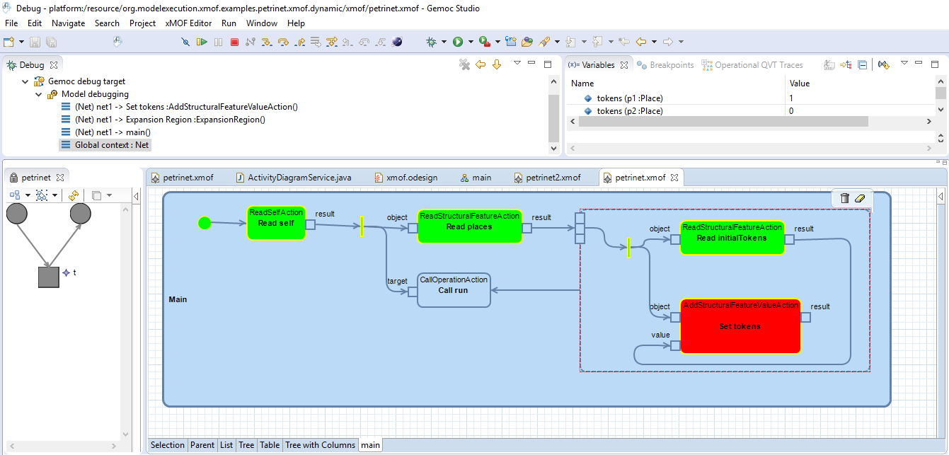
The aim of this project was to build a prototype of a model animator for xMOF models to improve the tool support for xMOF. This animator extends the debugging functionality of the Moliz model execution engine by interpreting debugging events to retrieve information about the current execution state of the model and using this information to visualize the state in the graphical representation (in this case activity diagrams). The animator supports node-wise stepping of xMOF activities and animates the activity diagrams to give the language designer a visual feedback about the state of the ongoing execution. To facilitate the integration into the Moliz project the model animator is implemented as an Eclipse plug-in. We implemented the animation in Graphiti and Sirius to demonstrate the differences between the two approaches.

Animation with Graphiti

In Figure 1 we see the Graphiti-based animator during the execution of a Petri net. As we can see in the bottom right, the nodes of the activity diagram are animated. Even after the end of an activity they are still animated for better traceability. They will only be reset if the activity diagram is executed again.

Animation with Graphiti
Figure 1: Animation with Graphiti

Animation with Sirius 

In Figure 2 we can see the same model. This time it is animated with Sirius. Both animators provide comparable functionality, however, the Sirius-based animator provides a more sophisticated animation of activity diagrams.

Animation with Sirius
Figure 2: Animation with Sirius

Outlook 

The project should be extended in the future to further improve the tooling support. The following features are the most promising ones:

  • Animation support for simultaneously executing activities should be supported. In particular, if two or more caller execute the same activity, the current state of the diagram is currently overwritten by the newest caller.
  • Interactive stack traces are a useful addition to give the possibility for navigating between activity diagrams.
  • The Sirius editor should be capable of representing all xMOF metaclasses. At the moment only the Activity metaclass and associated elements are represented.
  • A better mapping algorithm should be implemented to guarantee a correct mapping between model elements and diagram elements. At the moment the name property of an element needs to be unique. A violation of this constraint can cause unexpected behavior.

Implementation

The source code of the project can be found on Github.

Tuesday, July 19, 2016

Modernizing Software Languages through the Application of Model-Driven Engineering

From XML Schema to Xtext

By Agnes Fröschl, Bernd Landauer, and Bernhard Müller.


Introduction

Since the invention of Extensible Markup Language (XML) [Harold], it has gained a great popularity. The language is nowadays used as configuration and exchange format for a vast amount of applications. Some examples are the GPS Exchange Format (GPX), Scalable Vector Graphics (SVG) or configuration files for Computer Numeric Control (CNC) machines for production data. To make sure a provided XML file is valid, XML Schema Definition (XSD) [Gao] was introduced. However, XML and XSD are both optimized for machine processing and not human readability [Badros].

To bring language engineers, i.e., for example, the person who designed the instruction reader for a CNC machine and domain experts, i.e., for example, the person who operates the CNC machine, together, the XMLText Framework [Neubauer] has been introduced. It provides a transformation from XSD to Xtext-based Domain Specific Language (DSL) [Eysholdt, Tolvanen] with a more comprehensive and easily human readable concrete syntax.

In this work, we describe various XSD features that are not yet supported or limited by the XMLText transformation as well as our efforts to extend it [3]. The target is to escape fixed concrete syntax and provide an easy to use and customizable syntax for non-language engineers. Another important key feature is to keep backward compatibility, such that systems, which rely on XML files as an input source, do not need to be adapted to fit the new syntax.


Extension of the XMLText framework

Although some features are already implemented in XMLText, XSD provides an extensive amount of advanced features, for which support has still to be created. Our work mainly focused on extending the Ecore and Xtext Grammar generation.

Data types were our first area of contribution. Instead of proper Xtext Terminals, only stubs were created. We implemented valid Terminals for various data types. With this extension, only minor efforts were necessary to implement the support of various length restrictions for strings.

A more advanced feature was the implementation of mixed content, i.e., the support for the mixed=true XSD attribute. This construct allows the mixing of various newly defined elements in the created syntax or, in other words, text content with arbitrary text elements between tags.

Finally, we implemented ID and IDREF to ensure unique values for certain elements to which others can refer to. The related features KEY and KEYREF have been examined but their support has not been implemented due to the usage of complex XPath rules which are beyond the scope of our project.


Concrete Syntax DSL

Making the concrete syntax DSL even more readable and customizable, we explored the possibilities of Xtext to adapt the concrete syntax and style the appearance in the editor.

The figure below shows an example how a customized concrete syntax for a company hierarchy could look like. Other implemented extensions can be seen too, like date data type which yields an error if the date is not valid, e.g. month greater than 12. Auto-completion for IDREF values referencing available ID values. An arbitrary text content element between the named tags.

customized concrete syntax DSL


Future Work

The XMLText framework targets a quite complex problem, not least because of the feature richness of XSD and respectively XML. There are several topics for further extensions. Future work may include following Topics:
  • Implementation of further XSD features closing existing gaps,
  • an XPath to OCL [Warmer] converter to fully support for example KEY and KEYREF XSD features,
  • a fully automized generation of customized concrete syntax DSL, which includes a configuration wizard for syntax adaption,
  • and a CSS interpreter for concrete syntax DSL styling.


Resources

[Badros] Badros, G.J.: JavaML: A Markup Language for Java Source Code. Computer Networks 33(1), 159-177 (2000).
[Eysholdt] Eysholdt, M., Behrens, H.: Xtext: Implement your Language Faster than the Quick and Dirty Way. In: Companion Proc. of OOPSLA. pp. 307-309. ACM (2010).
[Gao] Gao, Shudi, et al. W3C XML schema definition language (XSD) 1.1 part 1: Structures. In: W3C Candidate Recommendation 30.7.2 (2009).
[Harold] Harold, E.R., Means, W.S., Udemadu, K.: XML in a Nutshell, vol. 8. O'reilly Sebastopol, CA (2004).
[Neubauer] Neubauer, P., Bergmayr, A., Mayerhofer, T., Troya, J., Wimmer, M.: XMLText: From XML Schema to Xtext. In: Proceedings of the International Conference on Software Language Engineering. pp. 71-76. ACM, New York, NY, USA (2015).
[Tolvanen] Tolvanen, J., Kelly, S.: De ning domain-speci c modeling languages to automate product derivation: Collected experiences. In: Proc. of SPLC. pp. 198-209 (2005).
[Warmer] Warmer, Jos B., and Anneke G. Kleppe. The Object Constraint Language: Precise Modeling With UML. In: Addison-Wesley Object Technology Series (1998).

XMLText framework website: http://xmltext.big.tuwien.ac.at/
XMLText framework source code: https://github.com/patrickneubauer/XMLText
XMLText framework fork including extensions: https://github.com/syrenio/XMLText

Monday, July 18, 2016

Context Modeling and Analysis of Cyber Physical Production

Christian Proinger 

Introduction

Cyber-physcial Systems (CPS) are a composition of computational entities that are able to sense parameters of the physical world and its processes. They are provide and use services available on the internet. Cyber-physical production systems (CPPS) specializes this concept to the domain of production across all levels, from processes through machines up to production and logistics.

The problem we are addressing is the modeling and analysis of context-aware systems from requirement specification and early design to system deployment or commissioning.

In [1], a multidimensial context model is represented through a set of composable probabilistic state machines (called First-Order managers (FOMs). Dependencies among FOMs are represented through cause-effect relationships called remote firings. The composition of multiple dependent FOMs results  in a Higher-Order manager (HOM). Both FOM and HOM correspond to Continuous Time Markov Chains (CTMC). 
In order to support the approach presented in [1], we implemented an Eclipse based graphical editor for modeling i) FOMs, ii) their composition and iii) HOMs. For analyzing the CTMC model we implemented a code generation feature that generates the input for the Probabilistic Symbolic Model Checker (PRISM). The following figure shows an overview of the process we facilitate with our implemented tools.

Case Study: Factory Operator 

As a running example we consider a factory with three rooms (named A, B and C). Further consider a machine (machine A) that is located at room A in that factory that produces a
certain kind of product. After turning out a certain amount of items it enters a phase of self-maintenance where it checks if its tools need replacements or some re-calibration is necessary. Completing this process after every item would be too time consuming so the time span between self-maintenance phases is adjusted to be optimal in respect to the price of the raw goods and the probable amount spoilage it will produce when self-maintenance would become necessary during
a production phase.
The scenario additionally involves a human operator who was instructed to cycle through three specific rooms of the factory throughout her work schedule. The operator is expected to be at work for a certain amount of hours during work days. Her task is to maintain machines that encounter a problem during a self-maintenance phase that they can not resolve by themselves.
 One question about such a scenario we would like to be able to answer now is: ”How likely is it that, while machine A is in its self-maintenance phase, the operator is in exactly the same room?”. Another question might concern the probability of the human operator at least being at the factory and not at home. 

Context Modeling

To be able to reason about the factory operator case study we apply the framework introduced in [1], which allows to model different types of actions and context-awareness and their dependencies with a stochastic extension of UML state machines, called Managers. The model, which is annotated with performance characteristics is used to analyze properties of the system. First-Order Managers (they are called that because they are concerned with just a single context attribute) can be combined to get FOM-Composition models by introducing remote firing dependencies between them. The following diagram shows the Eclipse EMF meta model for the FOM-Composition.
The FOM-Composition model, as well as FOM models can be modeled with the Eclipse plugins we implemented. The following image illustrates how the FOM-Composition model for the factory operator case study looks like in our tool. 
From this model a context menu action, implemented as an Eclipse plugin, will let the user create a Higher-Order Manager (HOM) model. The HOM is obtained from the FOM-Composition model by using the cartesian product of the states of the source FOMs as states. The transitions in the HOM result from the transitions of the states that make up a combination-state and the remote firing relationships of these transitions. The HOM for the case study, that is created by our implementation, is shown in the following picture. 

Context Analysis

The HOM enables us to reason about the combined context and its evolution. By applying the stochastic process of Continous Time Markov chains (CTMC) we obtain transient- and steady-state probabilities for the combined states. To calculate these probabilities we chose to use PRISM[2]. PRISM takes a text file as an input that conforms to their DSL that describe CTMCs. We implemented an Eclipse plugin to generate this DSL file from a HOM model. The following image shows the PRISM GUI and contains the DSL translation of our HOM.
For our case study PRISM will provide us with the following values enabling us to answer the question initially stated: ”How likely is it that, while machine A is in its self-maintenance phase, the operator is in exactly the same room?”


References

[1]  Berardinelli, L., Cortellessa, V., and Di Marco, A. Fundamental Approaches to Software Engineering: 13th International Conference, FASE 2010, Held as Part of the Joint European Conferences on Theory and Practice of Software, ETAPS 2010, Paphos, Cyprus, March 20-28, 2010. Proceedings. Springer Berlin Heidelberg, Berlin, Heidelberg, 2010, ch. Performance Modeling and Analysis of Context-Aware Mobile Software Systems, pp. 353–367.
[2] PRISM - Probabilistic Symbolic Model Checker. http://www.prismmodelchecker.org/.